


Distribution of protected area into the lightning protection zones
Distribution of protected area into the lightning protection zones
The standard IEC 13 12-1 and IEC 62 305 defines the lightning protection zones LPZ from the
respect of the direct even indirect lightning effect. These zones are characteristic thanks to
fundamental breaks of the electromagnetic conditions in their limited zones.
LPZ OA
Zone where items are subject to direct lightning strokes, and therefore may have to carry
up to the full lightning current; the unattenuated electromagnetic field occurs here.
LPZ OB
Zone where items are not subject to direct lightning strokes, but the unattenuated electromagnetic
field occurs
LPZ OC
Zone where items are not subject to direct lightning strokes and where currents on all
conductive parts within this zone are further reduced compared with zones 0B. In this zone the
electromagnetic field may also be attenuated depending on the screening measures
LPZ 1 Zone where items are not subject to direct lightning strokes and where currents on
all conductive parts within this zone are further reduced compared with zones 0B. In this zone
the electromagnetic field may also be attenuated depending on the screening measures
LPZ 2 Zone where items are not subject to direct lightning strokes and where currents on all
conductive parts within this zone are further reduced compared with zones 0B. In this zone the
electromagnetic field may also be attenuated depending on the screening measures
If a further reduction of conducted currents and/or elec-tromagnetic field is required, subsequent
zones shall be introduced. The requirement for those zones shall be selected according to the
required environmental zones of the system to be protected. In general, the higher the number of the
zones, the lower the electromagnetic environment parameters. At the boundary of the individual zones,
bonding of all metal penetrations shall be provided and screening measures might by installed.
Note: Bonding at the boundary between LPZ 0A, LPZ 0B and LPZ 1 is defined in IEC 13 12-1
and IEC 62 305. The electromagnetic fields inside a structure are influenced by opening windows,
by currents on metal conductors (e.g. bonding bars, cable shields and tubes), and by cable routing.
The following figure shows an example for dividing a structure into several zones.
There all electric power and signal lines enter the protected volume (LPZ 1) at one point, and are bonded
to bonding bar 1 at the boundary of LPZ 0A, LPZ 0B and LPZ 1. In addition, the lines are bonded to the
internal bonding bar 2 at the boundary of LPZ 1 and LPZ 2.
Furthermore, the outer shield 1 of the structure is bonded to bonding bar 1 and the inner shield 2 to
bonding bar 2. Where cables pass from one LPZ to another, the bonding must be executed at each boundary.
LPZ 2 is constructed in such a way that partial lightning currents are not transferred into this volume
and cannot pass through it.
The above described segmentation of the protected ob-ject into protection zones gives possibilities of
active protection of the LV power system thanks to insertion of the protective SPDs (usually at the
zone boundary LPZ 0→1and LPZ 1→2) and other protective SPDs at the zone boundary LPZ 2→3. Standardly
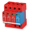
it is recommended to insert so-called 1ststage protection – surge arrester class I tested by lightning
current Iimp(10/350) at the zone boundary LPZ 0→1. It is recommended to insert 2nd stage
protection - surge arrester class II tested by testing impulse Imax(8/20) at the boundary zone LPZ 1→2.
At the boundary of LPZ 2→3 and subsequently along the consequential circuit there is also recommended
to shoulder after every cca 10m by socalled 3rd stage protection class III also tested by testing
impulse Imax(8/20) or UOC. For extra important protected equipment it is recommended to secure it by a
quality continuous surge protection class III with high-frequency filter at the boundary of LPZ 2→3.
If there are adjacent structures between which power and communication cables pass, the earthing system
shall be interconnected, and it is beneficial to have many parallel paths to reduce current in the cables.
A meshed earthing system fulfills this requirement. The lightning currents are further reduced, e.g.
by enclosing all the cables in metal conduits or gridlike reinforced concrete ducts, which must be integrated
into the meshed earthing system.